Catalog
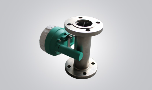
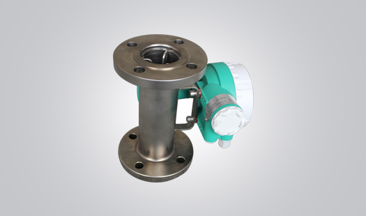
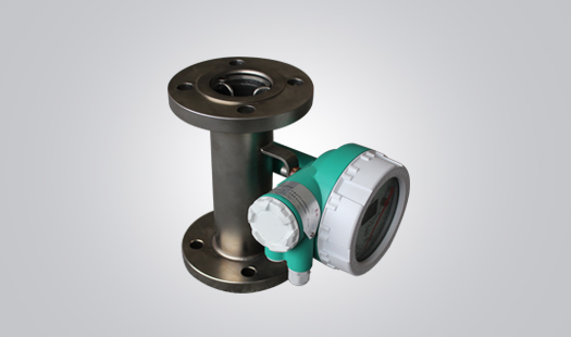
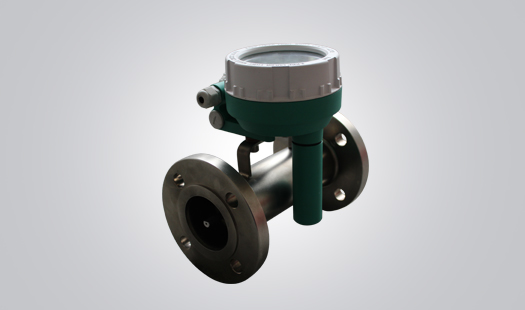


TFLC Series Metal Tube Rotameters
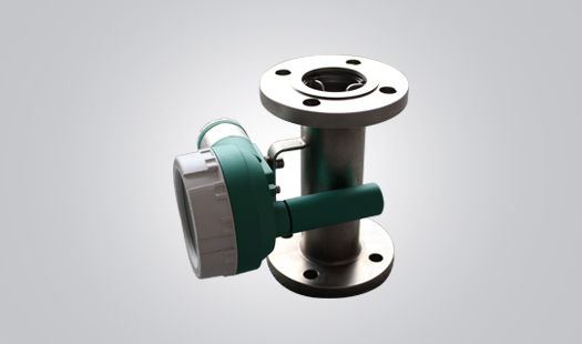
Fully Functional Volumetric Flow Measurement- Overview
- Brief Tech-Parameter
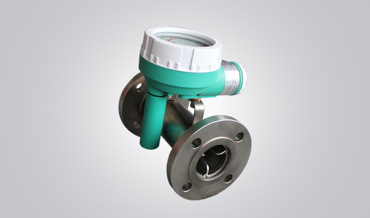
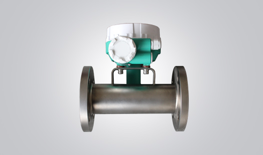
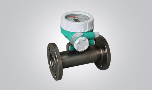
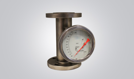
TFLC is specialized in Pipe flow measurement of Liquid, Gas and Steam. According to the pushing force of the media, the float inside TFLC will move a distance which is in proportion to the pushing force. The Magnetic Drive System of TFLC will calculate the flow value. The flow value can be directly shown on the Dial Indicator of the enclosure, or can be processed by the TFLC PCB and output current signal. In addition, TFLC is available for setting lower and upper flow-rate alarm.
- Well Stamping Molded and Polished, meet sanitary standard
- Intrinsic Safety + Explosive Proof, 4-20mA (2-wire) / HART
- Alarming Switch is optional
- Lithium Battery is optional
| Model | TFLC | |||||||
| Media Available | Liquid, Gas, Steam | |||||||
| Measuring Range (media in standard condition) |
Water: 20 0C | (10-300000) L/h | ||||||
| Air: 0.1013MPa, 20 0C | (0.7-3000) m3/h | |||||||
| Rangeability | 10:1 | |||||||
| Class of Accuracy | On-Site Type | Mechanical Dial Display | 1.0 F.S, 1.5 F.S, 2.0 F.S, 2.5 F.S | |||||
| Digital Display / (optional for battery, 2 years) | 1.0 F.S, 1.5 F.S, 2.0 F.S, 2.5 F.S | |||||||
| Remote Type | (Mechanical Dial + Digital) Display | 1.0 F.S, 1.5 F.S, 2.0 F.S, 2.5 F.S | ||||||
| Media Tempt. (0C) | On-Site Type | Mechanical Dial Display | -80 0C to + 300 0C (PTFE: 0 to 80 0C), Max.400 0C | |||||
| Digital Display / (optional for battery, 2 years) | -40 0C to + 120 0C (PTFE: 0 to 80 0C), Max.400 0C | |||||||
| Remote Type | (Mechanical Dial + Digital) Display | -40 0C to + 120 0C (PTFE: 0 to 80 0C), Max.400 0C | ||||||
| Ambient Tempt. (0C) | On-Site Type | Mechanical Dial Display | -40 0C to + 120 0C | |||||
| Digital Display / (optional for battery, 2 years) | -20 0C to + 60 0C | |||||||
| Remote Type | (Mechanical Dial + Digital) Display | -20 0C to + 60 0C | ||||||
| Media Viscosity | DN15 | F15.00~F15.03η<5mPa.S, F15.04~15.30η<30mPa.S | ||||||
| DN25 | η<250mPa.S, F15.04~15.30η<30mPa.S | |||||||
| DN50~DN250 | η<300mPa.S | |||||||
| Nominal Pressure | DN15~DN50 | Standard: 1.6MPa~4.0MPa | Max. Pressure | DN15: 42MPa, DN25: 42MPa, DN50: 32MPa) | ||||
| DN65~DN250 | Standard: 1.6MPa | Max. Pressure | DN80: 10MPa, DN100: 6.4MPa, DN125: 4.0MPa, DN150: 4.0MPa) DN200: 2.5MPa, DN250: 2.5MPa |
|||||
| Process Connection | Flange, Standard: DIN2501, ANSI, JIS, as required | |||||||
| Sanitary Clamping, Threaded Connection, as required | ||||||||
| Electrical Connection | 1/2 NPT, 3/4 NPT, 1/2G, 3/4G, M20x1.5 | |||||||
| Installation Type | Vertical | Flow Direction: ↑, ↓ | ||||||
| Horizontal | Flow Direction: ←, → | |||||||
| Cross | Side in Bottom Out, Bottom in Side out | |||||||
| Inlet Pipe Diameter | ≥5D | |||||||
| Outlet Pipe Diameter | ≥250mm | |||||||
| Enclosure Protection Grade | IP67 | |||||||
| Explosive-Proof | Ex ia II CT5 | |||||||
| Ex d II CT6 | ||||||||
| Intrinsic Safety Parameter | Ui=28V Ii=93mA Pi= 0.65W Ci≤ 5nF Li =0mH | |||||||
| Safety Barrier Parameter | Uo≤ 28V Io≤ 93mA Po≤ 0.65W Co≥ Ci+Cc, Lo≥ Li+Lc | |||||||