News
Overview of Tosilon’s Coriolis Mass Flow Meter
Publisher:Tosilon
Features
· Coriolis Mass Flow Meter could directly measures the mass flow with high accuracy.
· Available for the measurement of both “Newtonian Fluid” and “Non-Newtonian Fluid”.
· Competent to the measurement of highly viscous liquids, liquids with solids and liquids with small quantity gases.
· Competent to the measurement of high pressure gases.
· The amplitude generated by the resonating tubes is tiny. No “Moving Parts” could be regarded for the measuring tubes.
· Insensitive to fluids’ velocity, no requirements on “straight pipe” for up/downstream.
· Insensitive to fluids’ viscosity, the changing density has little influence on the flow metering.
· Multi-functional, solute concentration could be calculated by transmitter based on values measurement.
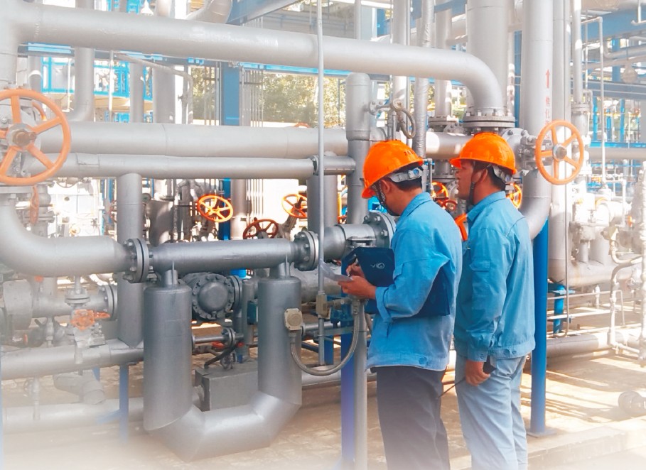
Installation of Coriolis Mass Flow Meter
In order to have the coriolis mass flow meter worked with excellent performance, the followings are the crucial elements including “Mechanical Installation”, “Electrical Installation” and “Maintenance”.
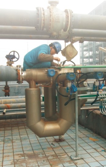
- Installation
a. The flow sensor should be installed supported by firm frame.
For small sized flow meters (≤10mm), the flow sensor should be installed on “anti-vibration” bases such as wall or ground.
For application where high vibration exist, the supporting frame should be considered absorbing the vibration. It is better to adopt metal hose as process connection.
For large sized flow meters’ installation, the flow sensor should be firmed fixed by pipe strap and supporting frame.
b. In order to avoid the deposition of liquids, the sensor must be installed with the measuring tubes are at the down-position or applying the vertical installation, meanwhile please confirm the Sensor installed at the lowest part of the
pipeline. When measuring gas, the Sensor should be installed in the Upper position, meanwhile confirming the Sensor is not installed at the lowers part.
- Operation
1. Zero Adjustment
Turn off the downstream valve when the flow sensor is fully filled by medium. Perform “zero adjustment” when the temperature meet the working temperature. Make sure the valve is fully turned off during the “zero adjustment, otherwise, it will cause big error.
2. Flow & Density Calibration Coefficient Setting
Flow Calibration Coefficient includes the sensor sensitivity and flow temperature coefficient. Sensitivity indicates the flow value measured of each microsecond. Flow temperature coefficient indicates the degree of influence of the sensor’s elasticity modulus caused by temperature.
Density Calibration Coefficient indicates density temperature coefficient and the sensor’s natural vibration period under 0 Deg. C when the measuring tube is filled by air or water. The setting is crucial to density accuracy.